
Using LED or character LCD displays is quite simple. However 7 segment LCD displays are very nice too and look just that bit more professional and
use far less power. The only disadvantage is that they are "difficult" to use because a) they need AC instead of DC to drive and b) they are usually
not configurable as matrix and thus need a lot of IOs. There are custom ICs available to do this task but who wants to use some fancy, hard to get IC
if it can be done with a normal, cheap and much better AVR? This project is an assembler routine for normal AVR microcontrollers to control a 7
segment display with up to any number of segments/IOs that can be spared on the AVR.
Features:
- any pin can be assigned to any segment
- uses less than 0.3% CPU load at 1MHz
- uses less than 200 words of program memory
- scanned at 30Hz
- generator spreadsheet to generate segment data
- written with the Algrom Assembler
- runs on any AVR
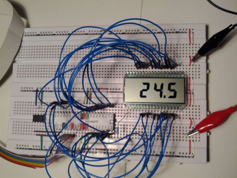
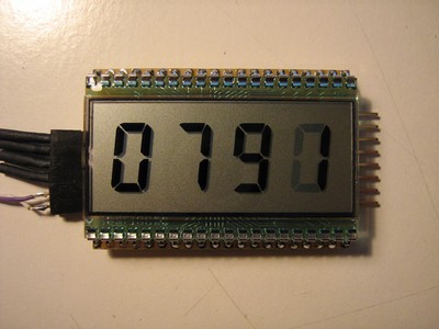
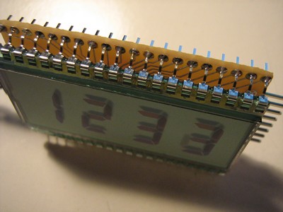
Test circuit: a thermometer with DS1621
The driver uses less than 0.3% of the CPU time running at 1MHz. The AC has a frequency of 30Hz which turned out to be totally adequate for a flickerfree
display. The pins that drive the segments can be chosen freely across all the ports. They do not need to be on one port for one digit nor do they need
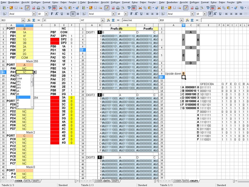
to be on the same portpin for each segment. All unused portpins can be used for something else. A calculator spreadsheet is used to decode the segment
and port information. This is then exported in data files which are included in the driver.
 A pseudo AC is generated by simply inverting the polarity of the backplane (COM) and the segments. Visible segments have the opposite polarity to COM,
invisible ones have the same. This is needed because the crystal segments get saturated with DC and fade out.
A pseudo AC is generated by simply inverting the polarity of the backplane (COM) and the segments. Visible segments have the opposite polarity to COM,
invisible ones have the same. This is needed because the crystal segments get saturated with DC and fade out.
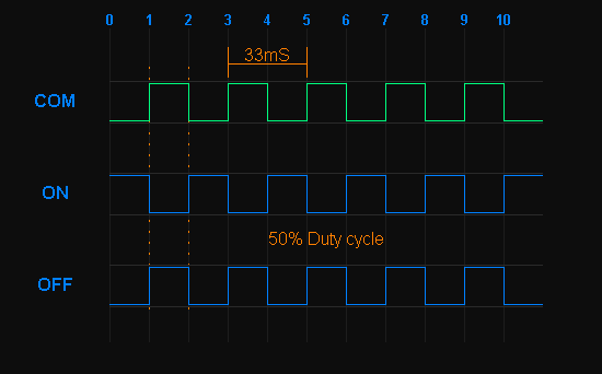
"digital AC" for displays with common backplane
The ultra compact module based on the LCD driver. It has a UART and I2C interface for general purpose use.
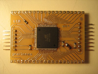
The circuit side with ATmega64
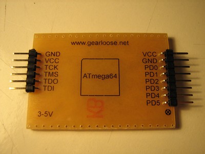
The back with pin description
The ultra compact module
Hardly bigger than the LCD itself
Features:
- any pin can be assigned to any segment
- uses less than 0.3% CPU load at 1MHz
- uses less than 200 words of program memory
- scanned at 30Hz
- generator spreadsheet to generate segment data
- written with the Algrom Assembler
- runs on any AVR
Test circuit: a thermometer with DS1621
"digital AC" for displays with common backplane
The circuit side with ATmega64
The back with pin description
The ultra compact module
Hardly bigger than the LCD itself
|
LAST
|
NEXT
|